Guides & Articles
Insights From the JT-NM Tested Program Why Test ST 2110 Devices?
Why Test ST 2110 Devices?
JT-NM Tested: A Good Place to Start
Insight 1: Build the Ideal Test Environment
Insight 2: Conduct Network Connectivity Tests
Insight 3: Check SDP File Syntax
Insight 4: Setup for Difficult High-Bandwidth PCAP Captures
Insight 5: Analyze with EBU List
Insight 6: Find a Reliable Sender
Insight 7: Choose Your ST 2022-7 Level of Testing
Identified Challenge: What is a Reference Sender?
Why Test ST 2110 Devices?
A SMPTE ST 2110-networked environment must deliver all of the benefits of an IP infrastructure – with the predictability of SDI – in order for it to be useful. This challenge can be met only when the infrastructure is well-managed and edge devices respect specifications. A rogue ST 2110 device may not deliver as expected, which would be bad enough. More importantly, it could adversely affect other functioning devices and lead to unpredictable general failure, which could be catastrophic.
With this in mind, the first step to take after acquiring a new ST 2110 device for a broadcast network is to make sure that it is a good “network citizen.” A good network citizen will not affect the network or disrupt operations when it is directly connected to an on-air production environment. The second step is to actually test the promised functionality and its compliance to SMPTE standards and industry norms. For example, a production environment that is architected around ST 2022-7 redundancy would be very poorly-served if devices do not actually support the ST 2022-7 specification properly – which could ultimately lead to disruptions.
It is important to understand that some devices might actually work well in a small synthetic setup, but fail when put into a real working environment. Due to a number of unaccounted variables, a simple pass-fail test may not be sufficient to make informed decisions on choice of equipment. For example, network packet timing is very different when several transmitters are sending to one receiver compared to a single transmitter sending to a receiver. The timing of a sender is also different if it sends a single ST 2110 flow vs. several flows. Another typical testing pitfall is the dependence on one kind of transmitter. A receiver might work great with a narrow gapped transmitter – like an SDI-to-IP gateway – but not work well with a wide linear transmitter.
At first glance, issues like these may not appear to be a problem if the environment may only contain narrow gapped devices. However, knowing the functional boundaries of a working environment is critical to maintaining future expansion. Misinformed decisions taken today may limit future capability and possibilities, (e.g. supporting wide senders). To pre-empt this, it is advisable to build up a test suite that pushes the test boundaries for imperfect, but sufficiently good cases. It is only with these types of tests that informed decisions could be made, eventually leading to judicious ST 2110 device purchases, safe device firmware/software updates, and beneficial service agreements.
JT-NM Tested: A Good Place to Start
The JT-NM Tested program covers many areas including NMOS support, TR-1001 compliance, network security, and ST 2110 compliance. In this document, the focus will be on the JT-NM ST 2110 test plan and how users might leverage it as a basis for building their own test plans.
One of the main objectives of the JT-NM Tested program is to test workflows that address the deployment needs of broadcasters, help them understand which features are supported by ST 2110 devices, and whether or not these features are well-supported. Though these tests were created in consultation with industry experts, they maintain neutrality as they are administered by the European Broadcasting Union (EBU) and the Broadcast Technology Institute (IRT). This program is driven by the needs of customers, not by manufacturers. The test plan covers what needs to be tested, contains details on how to execute the tests, and includes clear pass-fail criteria. The test plan also suggests tools that can be used to execute some of these tests.
Various test plans can be found on the JT-NM Tested program page. The goal of the program is to generate a catalog that lists the results of various tests on listed devices. The JT-NM Tested program has been active for a few years now, and links to different catalogs that were generated at past events can be found. For each event, the JT-NM expert group tries to improve and update the test plans. Test plans can be found at the beginning of each catalog. This whitepaper references the Spring 2020 Self-Tested SMPTE ST 2110 Catalog (May 2020). The JT-NM test plan covers video, audio, and ancillary data separately. They will be covered together in this document since they are essentially the same.
This white paper will highlight some key insights to quickly reap the benefits of this valuable multi-faceted industry effort.
Insight 1: Build the Ideal Test Environment
A separate test environment should be built to conduct tests. Not only are some of the tests disruptive to a production environment, but it is also not advisable to connect a device directly to a production environment before it has been screened. A test environment should have similar characteristics to the production environment.
For example, if boundary switches, Dynamic Host Configuration Protocol (DHCP), and Software-defined Networking (SDN) are used in production, then the test environment should incorporate the same elements where possible. Some setups that offer ST 2022-7 support have redundant PTP Grandmaster clocks, so it might be hard to justify building a test network that supports that level of complexity. For most tests, this specific case is not an important factor, and a simpler network topology can be used.
Some tests will require capturing PCAP (packet capture) files, which contain the network packet data that was present on the network. These files can be used for packet analysis -- which is key in testing/debugging ST 2110 flows. Knowledge of how to set up monitoring sessions on the network switch will also be very useful. Users are well-advised to be comfortable setting this up on their switch.

Insight 2: Conduct Network Connectivity Tests
The test plan starts with basic network connectivity tests where support for DHCP and IPv4 static configurations are tested. The “ping test” is critical, and many devices fail this test at first. This test ensures the device is capable of working in one subnet while being addressed from a separate one.
For ST 2110 receivers, it is important to make sure IGMPv3 is used. When a network uses IGMPv3, a single device using IGMPv2 can disrupt the whole network. Though IGMP may not be needed in an SDN environment, it is important to make sure the device being tested supports IGMP as it is mandated by the SMPTE ST2110 suite of specifications.
Insight 3: Check SDP File Syntax
SMPTE ST 2110-10 stipulates that senders must generate a Session Description Protocol (SDP) file that describes the ST 2110 signal. The SDP files should describe the associated ST 2110 flows and provide session description metadata irrespective of the transport and the media itself.
For validating SDP files, the SDPoker application is used. SDPoker is an open-source software that was developed to meet industry needs and verifies that the syntax of the SDP file follows the specification. It does not ensure that the IP addresses in the SDP file match those generated by the sender; it only ensures that there is an address in the SDP file and that it is written correctly.
SDPoker requires Node.js to be installed on a computer. It is a simple install process, but is not covered by the test plan. One thing to know before getting started is that SDPoker only outputs messages when it finds errors. To test an installation, it is advised to use an SDP file in which an error has been purposefully introduced. Different interpretations of the specifications have led to a myriad of SDP file inconsistencies, making this test extremely important to ensure proper flow management.
Insight 4: Setup for Difficult High-Bandwidth PCAP Captures
A basic sender test includes connecting a known ST 2110 receiver to allow for visual monitoring. However, the main sender tests mostly concentrate on capturing the ST 2110 signals from the sender as PCAP files.
Capturing a PCAP file of an ST 2110 signal can be difficult. When dealing with uncompressed ST 2110-20 video, the data rate required can be high. For a UHD signal at 59.94 Hz, the bandwidth hovers around 11Gbps or 1.4GBps. Not only do these captures require high-bandwidth capture to disk without packet loss, but they also require high-precision timestamping for proper post analysis for compliance – both of which are not easy to accomplish without specialized equipment.
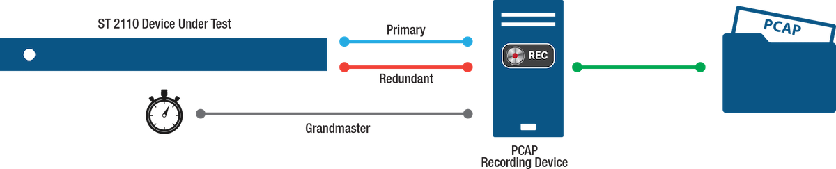
Please note that ST 2022-7 testing adds further complexity where double the bandwidth is required for primary and redundancy captured PCAP file. It is worth noting that, given proper timestamps, a separate file can also be suitable for this test.
Insight 5: Analyze with EBU List
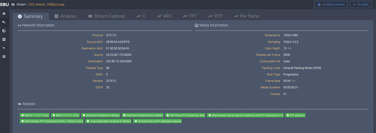
Once the challenge of capturing accurate and representative PCAP files is completed, these files should be loaded in EBU’s Live IP Software Toolkit (LIST). LIST is another industry-specific, open-source application. It analyzes PCAP files and reports any specification compliance issues it finds. LIST is an easy and intuitive tool to use. However, it can be a difficult to set up.
LIST is available as a Docker container or online. The online version requires uploading the PCAP file to the cloud for analysis. Depending on the organization’s network environment, this does not always work. The Docker container version requires installing Docker on the test system. Again, depending on the network environment, this might be challenging. LIST provides a summary of all of the tests it performs on the signal in the PCAP file and highlights the issues it finds. In the example below, it analyzed a 1920x1080p @ 59.94 signal and found no issues. The PCAP analysis tests should be done for various resolutions and for all video, audio, and ancillary flow types.
Side Note: For sender tests, random but valid multicast addresses and ports should be used. If also doing ST 2022-7 test, a separate address and port for the redundant channel will also be needed. Please note that different ports should be chosen to make sure they are fully configurable on the device even if they are the same in the real environment.
Insight 6: Find a Reliable Sender
Executing the receiver tests in the test plan will require access to a reliable sender. A reliable sender can be something as simple as a device that sends a valid signal. The receiver being tested will need to be programed to listen to the sender signal and ensure that the receiver is receiving the signal properly. Unfortunately, this is not a very scientific test, but alternatives are limited. Not much can be measured in this case; either the device works, or it does not. Having access to multiple reliable senders—including narrow and wide senders, and senders that can send multiple flows at the same time to simulate timing variations—would be an asset to increasing testing coverage.
Insight 7: Choose Your ST 2022-7 Level of Testing
As mentioned earlier, the basic ST 2022-7 sender tests are done at the same time as the regular sender tests. The ST 2022-7 receiver tests are broken down in two categories: basic and advanced. The basic tests can be done in the lab without any specialized equipment. An ST 2022-7 reference sender will need to be set up, and the receiver will need to be programmed to listen to the signal. Then, one of the two media interfaces will need to be disconnected. As long as one of the two media interfaces remains connected, there should be no disturbance in the received signal. The signal can be disconnected either by unplugging the connector or by turning off the port in the switch. It is important to leave enough time after re-connecting the signal for things to go back to normal. It is also necessary to wait for the network switch to re-negotiate the connection before getting the DHCP address back, getting the IGMP to flow again, and then finally disconnecting the other side (to test both connections).
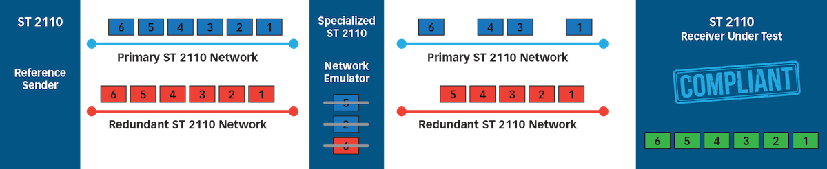
The advanced test involves putting a network emulator in the path between the sender and the receiver to generate more dynamic errors in the flow. Again, it is important to make sure the receiver is able to retrieve the signal without disturbance. The network emulator is able to generate much better granularity of the test signal. It can switch the signal on and off at a packet boundary, and does not have to wait seconds between disturbing one side of the signal versus the other.
Identified Challenge: What is a Reference Sender?
During the development of the receiver test plan, it became obvious to the expert group that using a perfectly compliant ST 2110 signal is not sufficient to test receivers. The concept of a reference sender that can be programmed to generate the different combinations of valid ST 2110 signals was identified as a key missing component to being able to confidently test receiver compliance. A reference sender can be defined as an ST 2110 flow generator that:
- Provides narrow, narrow-linear, and wide packet timing.
- Simulates typical signal delays that can occur in a production network.
- Generates both a perfect signal in the middle of the target specification, and a valid signal that hovers around the edges of the target specification.
In order to certify a receiver, it is important not only to use a reliable sender, but also to use an actual reference sender. The receiver under test should be tested to support the full specification, not just show that it can receive a perfect signal.
As part of Matrox’s development of multiple generations of ST 2110 Network Interface Controller (NIC) cards, our labs were quickly filled up with various homegrown tools that enable internal validation and subsequent participation at the JT NM Tested programs. These tools, built out of necessity, have played an important role in the deployment of solid ST 2110 devices. In consultation with partners demanding to have access to these tools, Matrox has packaged these into a 1-RU appliance.