Guides & Articles
Matrox PCI and PCIe Guide
Matrox Guide to Different Types of Expansion Slots and Add-In Cards
Matrox makes a variety of graphics cards designed to be inserted into certain types of computer expansion slots. The most common slot types used by graphics cards are PCI™ and PCIe® and for each of these types, there are also several sub-types. The different slot types available are an important consideration when buying a graphics card or computer. This guide describes the differences between these slot types and their sub-types.
PCI
PCI (Peripheral Component Interconnect) is a type of computer bus for attaching or inserting peripheral devices into a computer. The PCI standard was first proposed by Intel in 1990 and was widely implemented in computers by 1995. Today, the specifications for PCI and its variants are maintained by the PCI-SIG® (PCI Special Interest Group), a consortium of over 700 companies.
PCI is a general-purpose connection standard designed to support multiple devices of various kinds, including graphics hardware, audio hardware, network hardware, and so on. Revisions of the PCI standard have added new features and performance improvements, including different bus speeds and bus widths. Below is a summary of the different potential bandwidths for the most popular variants of the basic PCI standard.
| Bits / connection | MHz | Potential bandwidth (MB/s) |
|---|---|---|
| 32 | 33 | 133 |
| 32 | 66 | 266 |
| 64 | 66 | 532 |
These various types of slots and expansion cards are generally compatible with each other. However, unless a card and slot are designed to use a wider bus (that is, 64 bits) or a faster bus speed (66 MHz) they generally default to the lower setting.
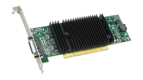
For example, a 64-bit PCI card like Matrox P690 Plus LP PCI has an edge connector that's wider (longer) than for a 32-bit PCI card like Matrox G450x4 MMS. Despite this, a 64-bit PCI card can be inserted into a 32-bit PCI slot. In this case, part of the edge connector simply overhangs the slot and only the first part of the edge connector is used (that is, only 32-bit communication occurs). By the same token, a 32-bit PCI card can be inserted into a 64-bit slot. In this case, the edge connector of the card will only fill part of the slot and the connection will be 32-bit.
There's also an extension of the PCI standard referred to as PCI-X (not to be confused with PCI Express). Cards and slots designed for PCI-X are capable of bus speeds higher than 66 MHz. PCI-X slots are commonly available in servers and high-end workstations. A 64-bit, 66 MHz PCI card is compatible with PCI-X slots and can run at 66 MHz in such a slot.
PCI cards and slots are keyed to support different voltages. PCI cards and slots may run at 5 or 3.3 volts. All currently shipping Matrox PCI cards are compatible with either voltage and are keyed accordingly.
PCIe
PCIe (PCI Express®) is the more recently introduced standard for connecting devices to computers. It's software-compatible with PCI but has higher potential bandwidth and greater flexibility than PCI. The PCIe specification is also maintained by the PCI-SIG.
PCI Express is a point-to-point serial transmission interface using high-speed differential signaling to enable high-performance transfer of data within systems. A connection between a PCIe device and the system is known as a "link" and this link is built around a dedicated, bi-directional, serial (1-bit), point-to-point connection known as a "lane". The initial PCIe specification defined a 2.5 Gb/s data transfer rate per lane, while second generation PCIe increased the data rate to 5 Gb/s. The third generation of PCI Express has further increased the data transfer rate to 8 Gb/s per lane of data A link can use more than one lane at a time but all links compliant with the PCIe specification must minimally support single-lane connections, referred to as "x1" (pronounced "by-one") links.
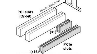
For higher potential bandwidth, PCIe devices and systems can optionally support links using multiple simultaneous lanes—for example, a "x16" link uses 16 lanes. To support extra lanes, a PCIe card and slot must be designed to accommodate the extra electrical lines required (2 lines per lane). Card and slot types exist for x1, x4, x8, and x16 links.
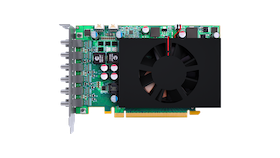
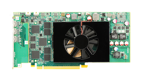
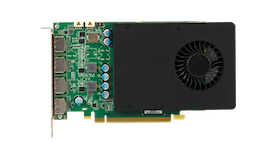
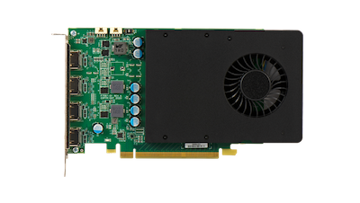
Matrox has several PCIe x16 graphics cards, including the quad-output D1450 PCIe x16, the D1480 PCIe x16, and the quad-output M9148 LP PCIe x16.
PCIe cards will physically fit into mechanical slots designed for their lane configuration or higher (up-plugging) but not into slots designed for lower lane configurations (down-plugging). So, for example, a x1 mechanical card will fit into x1, x4, x8, and x16 mechanical slots but a x16 mechanical card will only fit into a x16 mechanical slot. A x1 electrical card in any compliant PCIe slot will always run in x1 electrical mode. Matrox introduced the world's first PCIe x1 graphics cards, the Millennium G550 PCIe and Millennium G550 LP PCIe.
The internal architecture of PCIe is much like a local area network in that each link goes to a central hub in the computer that performs network-like switching. This is in contrast to the PCI architecture, where all devices share the same unidirectional, parallel bus. Because PCIe isn't based on parallel connections that can be hindered by timing issues, PCIe allows data to be more easily and cost-effectively transmitted over longer distances.
Potential Bandwidths of PCI and PCIe
The higher potential bandwidth that certain slot types provide don't necessarily result in proportionally higher performance. The bandwidth associated with each slot type is the maximum achievable and is subject to limitations due to software overhead (for example, operating system activity) and whether an application is maximizing usage. For example, a simple 2D application like a spreadsheet or word processing program is less likely to benefit from the advantages of this higher bandwidth. Intensive, real-time, 3D programs are more likely to use such extra bandwidth.
The differences in these bandwidths only affect the speed at which data is transferred between the graphics hardware and the rest of the computer. These bandwidths don't affect the speed of the graphics chip itself and don't directly affect the speed of the rest of the computer.
The PCI Express specification also defines backward-compatibility between PCI Express devices. That is, a device designed for Gen-3 PCI Express functions at Gen-2 speeds when connected to a Gen-2 device, a Gen-2 device functions at Gen-1 speeds when connected to a Gen-1 device, and so on.
The following summarizes the differences in potential bandwidth between the various slot types.
| Link width* | PCI-e Gen-1 | PCI-e Gen-2 | PCI-e Gen-3 |
|---|---|---|---|
| x1 | 250 MB/s | 500 MB/s | 1 GB/s |
| x4 | 1 GB/s | 2 GB/s | 4 GB/s |
| x8 | 2 GB/s | 4 GB/s | 8 GB/s |
| x16 | 4 GB/s | 8 GB/s | 16 GB/s |
-
The link width provides a measure of the data transfer capabilities of the link in a single direction. Since each PCI Express lane contains both an upstream and a downstream link, the effective bandwidth is doubled. The numbers in this table represent the maximum bandwidth available in each direction.
-
While the serial data rate has only increased from 5 Gb/s to 8 Gb/s over second generation PCI Express, the encoding of the serial data has changed, providing more efficient transfers and effectively doubling the data transmission rate over Gen-2 PCI Express.
PCI Express® Bandwidth Considerations When Capture Cards and Graphics Cards are in the Same System
Although the input resolutions and formats must be considered, the system bus-level architecture also plays an important role in optimizing the system for the best possible performance.
Input source bandwidth requirements
Any capture architecture receives its data from external sources and transfers it to one or more graphics engines for display. The inputs may take many forms: IP, DisplayPort, HDMI, DVI, analog RGB, component video, or even standard TV inputs using either composite or Y/C signals. Each of these inputs places a different load on the system in terms of quantity of data to be transferred.
The bandwidth required to transfer a captured stream within a computer system is dependent on input resolution, format and frame buffer organization. The input format refers to both pixel depth (8- or 10-bits) and pixel format (4:4:4, 4:2:2 or 4:2:0), and frame buffer organization is typically linear or planar. Although a frame buffer may be 24 bits, system transfers are performed in 8-, 16-, or 32-bit "chunks". The formula below provides an approximation of the bandwidth required from a given input stream, and assumes planar frame buffer organization.
In some cases, it may be possible to capture sources and transfer them internally using a 16-bit YUV format. Doing so will reduce the amount of system bandwidth required to transfer the input data, but it will also degrade the capture quality (since less data is being used to represent each pixel). This option should be used only when necessary, and with sources, where the quality of input capture can be sacrificed. The bandwidth required by any input source can be expressed as follows:
BW = resx x resy x fps x kpixel_factor
Where fps and kpixel_factor represent the number of frames per second and the number of bytes taken by each pixel, respectively. In analog RGB, component and DVI modes each pixel generally requires 4 bytes. In TV modes (or when data is represented as 16-bit YUV data) each pixel requires 2 bytes.
The table below provides a summary of pixel factors for different pixel depths and pixel formats.
| 4:4:4 | 4:2:2 | 4:2:0 | |
|---|---|---|---|
| 8-bit | 4 | 2 | 1.5 |
| 10-bit | 6 | 4 | 3 |
For example, a high-definition source being captured at 1920×1080p60 requires the following bandwidth:
BW 1080p = 1920 x 1080 x 60 x 4 ≈ 500 MB/s
An NTSC source at 60 Hz (interlaced) requires the following bandwidth:
BW NTSC = 720 x 480 x 30 x 2 ≈ 21 MB/s
Here are some examples of approximate bandwidths based on resolution/pixel formats:
| 4:4:4 | 4:2:2 | 4:2:0 | |
|---|---|---|---|
| 8-bit | 1000 MB/s | 500 MB/s | 375 MB/s |
| 10-bit | 500 MB/s | 250 MB/s | 185 MB/s |
For more information on video sampling and formats, see the following resources:
Regardless of the resolutions and formats of the various inputs, the available system bandwidth shouldn’t be exceeded. Doing so will result in reduced system performance and/or instability.
PCI Express architecture overview
To understand how system architecture plays a role in the available bandwidth, a basic understanding of the PCI Express architecture is helpful. This section provides a brief description of the PCI Express architecture to provide enough background to understand the bandwidth calculations provided later in this discussion.
To maximize data transfer capabilities within a system, having the largest lane widths possible throughout the system is preferred.
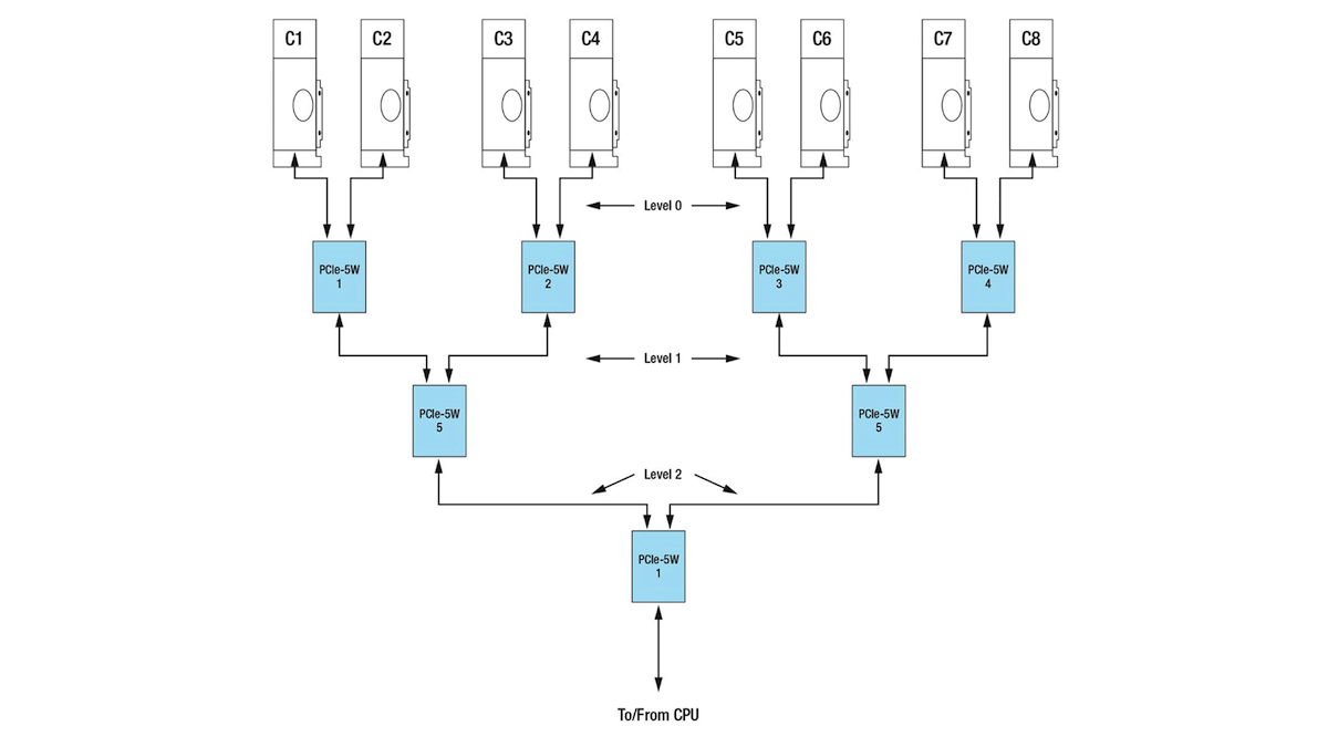
In the diagram above, assume that each PCI Express link is a ×8 connection operating at Gen-2 speeds. Each link thus has a total available throughput of 4 GB/s in each direction. Any combination of input streams being transferred through a given switch that results in the total bandwidth exceeding 4 GB/s will result in reduced system performance (stuttering playback and reduced frame rates).
When installing many cards in a system like this, it’s important to maximize transfer bandwidth. This is done by ensuring that capture cards are (as much as possible) not all placed on the same bus segments. Placing many capture cards on the same bus segment may create bottlenecks that can hinder performance and lower the overall capture rate. The manner in which inputs are mapped to output boards can also have an impact. When possible, inputs should be captured as close to the display card as possible to minimize system latency and maximize overall system bandwidth. As an example, in the above illustration, if the 3 Mura IPX Series cards on switches 1 and 2 are capturing data to be displayed on the Mura MPX Series card connected to switch 3, up to 9 GB/s of bandwidth may be required (depending on the number of inputs and their resolutions). This is above the maximum bandwidth of the bus segment connecting switches 5 and 7, and will result in performance issues (lower/stuttering frame rate transfer) or will require the data to be pre-scaled before its transfer to the output.
It’s impossible to cover all possible configurations of input and output cards in this page – indeed each situation will be different. However, knowledge of the system architecture and judicious placement of the capture and display cards based on the desired input/output mappings will allow virtually any bandwidth requirements to be met.
General bandwidth guidelines
Knowledge of the system architecture and the number and types of inputs is required to optimally place capture cards in the system. By carefully calculating the required bandwidth and ensuring that there are no data bottlenecks in the system, the integrator can guarantee the optimal functioning of his system.